


Switching your furnace lining from firebrick to ceramic fiber blanket is one of the few capital investments in furnace operations where the payback calculation is straightforward. Less heat loss = less fuel per cycle. The numbers are consistent across furnace types.
This guide is not about grade selection - if you need that, see our ceramic fiber blanket selection guide. This guide is about the design decisions that determine whether your CFB lining performs at specification or fails in 6 months: layer count, thickness calculation, density selection, anchor system, and the dry-out curve.
Why Ceramic Fiber Blanket Replaced Brick Backup in Many Furnaces
Three reasons drive the shift from traditional high temperature refractory bricks backup to CFB:
Heat storage. Firebrick has thermal mass - it absorbs heat during the heat-up cycle and releases it during cool-down. This is called heat storage loss. For a batch furnace with 8 heat cycles per day, each cycle charges the lining with heat that goes nowhere useful. CFB has 1/5 the heat storage of equivalent-thickness firebrick.
Thermal conductivity. 1260°C CFB at 128 kg/m³: 0.12–0.14 W/m·K at 400°C, 0.22–0.26 W/m·K at 800°C. Dense firebrick: 1.0–1.3 W/m·K at the same temperatures. CFB is 6–10× more insulating.
Weight. 150mm CFB lining weighs approximately 19 kg/m². 230mm firebrick lining: approximately 520 kg/m². For furnace shells with limited structural capacity, CFB enables higher temperature ratings without structural reinforcement.
Thermal efficiency comparison: Firebrick vs. CFB lining:
Furnace inner shell area: 20 m² benchmark
230mm firebrick wall: heat flux ~2,200 W/m², total heat loss 44 kW
150mm 128 kg/m³ CFB lining: heat flux ~950 W/m², total heat loss 19 kW
Net continuous thermal energy reduction: 25 kW (a 56% heat loss cut)
Furnace shell surface temperature: reduced from 110–135°C down to safe contact levels (50–60°C)
Operational payback: typically 2–4 operating months through direct fuel/power savings and significantly accelerated furnace heat-up cycles.
Lining architecture: Standalone CFB vs. composite backup: Ceramic fiber blanket can serve as the sole lining material in clean heat-treatment furnaces, annealing lehrs, and periodic ceramic kilns. However, it cannot stand alone where direct flame impingement, turbulent molten metal or slag contact, or mechanical scrap impact occur. In heavy melting furnaces, CFB is strictly specified as backup insulation behind dense refractory bricks or castables.
1260°C vs. 1430°C Grade - The Rating You Actually Need
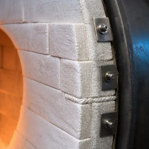
Temperature rating is a common source of over-specification. The rule: add 50°C safety margin above your measured hot face temperature.
1260°C grade (Standard): Al₂O₃ content 44–47%. For furnaces where the hot face temperature stays below 1210°C continuously. Ceramic kilns, heat-treatment furnaces, annealing furnaces, boiler insulation. Most common grade - best stock availability, lowest cost.
1430°C grade (High Alumina): Al₂O₃ content 52–56%. For furnaces with hot face temperatures up to 1380°C. Cracking furnaces, petrochemical reformers, rotary kiln backup, glass furnace upper structure. 20–25% premium over 1260°C grade.
1600°C grade (Low Shot Zirconia-enhanced): For very specific applications above 1400°C hot face temperature. Higher cost, lower availability. If your furnace reaches these temperatures at the hot face, consult us - this range often requires a composite lining design.
One honest clarification: The "classification temperature" on a CFB datasheet is the temperature at which the material shows ≤4% linear shrinkage after 24 hours. It's not the maximum continuous service temperature. In practice, operate 50–80°C below the classification temperature for sustained service.
Layer Thickness Calculation for Your Furnace Wall
The goal: determine CFB thickness to keep the outer shell temperature within an acceptable range (typically below 65°C surface temperature for personnel safety).
Basic heat flux formula:
q = ΔT / (Σ R_i) where: q = heat flux (W/m²) ΔT = temperature difference (furnace T – ambient T, in °C) Σ R_i = sum of all thermal resistances (each layer = thickness/conductivity)
Worked example:
Furnace temperature: 1200°C. Target shell surface temperature: ≤60°C. Ambient: 25°C.
Available thermal resistance needed: (1200 – 60) / (target heat flux)
For a 1200°C furnace, target heat flux at shell: typically 500–800 W/m².
Using 1260°C CFB at 128 kg/m³:
Thermal conductivity at mean temperature 600°C: approximately 0.22 W/m·K
Required thickness: (1200 – 60) / 800 W/m² × 0.22 W/m·K = 0.313 m → round up to 350mm
This is a simplified calculation. For accurate design, use the mean temperature for each layer with the conductivity at that temperature. If your furnace operates at variable temperatures, use the maximum operating temperature.
Practical thickness guidelines by furnace temperature:
| Furnace Hot Face Temp | Recommended CFB Thickness (128 kg/m³) | Expected Shell Temp |
|---|---|---|
| 800°C | 100mm (2 × 50mm) | ~50°C (or consider calcium silicate board backup) |
| 1000°C | 150mm (3 × 50mm) | ~55°C |
| 1200°C | 200mm (2 × 100mm) | ~55°C |
| 1350°C | 250–300mm composite lining | ~60°C |
Engineering note for 1200°C operation: A 200mm layered build (either 2 × 100mm or 4 × 50mm offset courses) of 128 kg/m³ CFB maintains cold-face shell temperatures at 50–60°C at 25°C ambient. If operating under frequent cyclic heating or tighter exterior temperature limits, expand total thickness to 250mm.
For composite linings above 1300°C: use 1430°C CFB for the inner layer (direct hot face), 1260°C CFB for the outer layer. This combines thermal performance with cost optimization.
Blanket Density: 96, 128, 160 kg/m³ - What Changes?
Three density options for the 1260°C grade:
96 kg/m³: Lowest density, lowest cost, lowest mechanical strength. Suitable for horizontal furnace walls and ceilings where blanket is compressed against anchors and not subject to airflow. Not recommended for applications with gas velocity >3 m/s over the lining surface.
128 kg/m³: Standard density - the correct choice for 90% of furnace lining applications. Better compression resistance, better surface stability, slightly higher thermal conductivity than 96 kg/m³ (not meaningful in practice). This is what we stock in depth.
160 kg/m³: High density for applications with gas erosion (combustion chamber near burner ports), vibration, or where CFB is used as hot-face material with frequent maintenance access.
Density and thermal conductivity: Counterintuitively, increasing density from 96 to 160 kg/m³ slightly increases thermal conductivity (more solid phase per unit volume). The difference is small - approximately 5–8% higher conductivity at 128 vs. 96 kg/m³. For most applications, this doesn't change the thickness calculation meaningfully.
Anchor System Design - Spacing, Material, Penetration Depth
The anchor system holds CFB blankets in place through thermal cycling. A failed anchor = a sagging blanket = localized hot spots and premature failure.
Anchor spacing:
| Application | Horizontal spacing | Vertical spacing |
|---|---|---|
| Wall lining (blanket vertical) | 300mm | 300mm |
| Ceiling/roof (blanket horizontal) | 250mm | 250mm |
| Near burner ports (high velocity) | 200mm | 200mm |
Use a staggered grid - anchor rows offset by half the spacing to distribute load evenly.
Anchor material by hot face temperature:
| Hot Face Temperature | Anchor Material | Selection Guidelines |
|---|---|---|
| Up to 900°C | SS 304 | Standard oxidation resistance |
| 900°C–1200°C | SS 310S | High-temperature austenitic steel; limit continuous service to 1150°C |
| Above 1200°C | Inconel 601 or Ceramic Anchors | Inconel prevents destructive scaling; high-alumina ceramic anchors withstand extreme heat without oxidation, though require vibration-free mounting |
Penetration depth: Anchor should penetrate at least 2/3 of total lining thickness from the cold face. For a 150mm lining: anchor 100mm from cold face (penetrates 100mm into the lining).
Installation note: Install anchors after the first blanket layer, not after all layers. Each layer gets its own set of anchors. For a 150mm lining (3 × 50mm layers): anchors at 50mm depth, then 100mm, then 150mm (shell attachment).

Installation Step-by-Step
Clean the furnace shell. Remove all loose scale, old mortar, and debris. Any high spots >10mm should be ground down.
Mark anchor positions. Use chalk line for uniform spacing. Drill and weld or bolt anchor bases to shell.
Install first blanket layer. Compression-fit blanket between anchors. Seams between blanket rolls should be offset from layer to layer - never align seams in adjacent layers.
Fold and tuck edges. At corners, fold blanket rather than cutting - this eliminates gaps at corners that become heat leak paths.
Install intermediate anchors. After first layer, install second row of anchors at depth = first layer thickness.
Repeat for subsequent layers. Offset seams by at least 300mm from previous layer seams.
Apply ceramic fiber rope at joints. Pack all expansion joints, around burner blocks, and at door frames with ceramic fiber rope compressed to 50% of rope diameter.
First heat-up (dry-out curve): CFB does not have the same dry-out requirement as castable refractories, but a controlled first heat-up is good practice:
Room temperature → 200°C at 50°C/hr
Hold at 200°C for 2 hours
200°C → operating temperature at 100°C/hr
Common Failure Modes - Why CFB Linings Fail Early
1. Anchor failure. Wrong anchor material for the service temperature causes oxidation and anchor fallout. In a 1200°C furnace with SS 304 anchors - these will fail within weeks. Use SS 310S minimum.
2. Blanket shrinkage at joints. At service temperature, CFB shrinks 1–3% linearly. Seams in adjacent layers aligned vertically create a through-gap after first heat cycle. Offset seams by minimum 300mm.
3. Gas erosion on the hot face. If gas velocity at the lining surface exceeds 3 m/s, use 160 kg/m³ density or protect the surface with a pre-compressed ceramic fiber module layer. Straight 96 or 128 kg/m³ blanket erodes rapidly in high-velocity gas streams.
4. Inadequate compression at corners and edges. Gaps at corners are the most common heat leak source. Fold and tuck the blanket at all corners - never cut it. Gaps = arc-like hot spots visible on thermal imaging.
5. Chemical attack from process gases. Some chemical environments (HF, strong alkali vapor) attack standard alumina-silica CFB. For these environments, use high-purity alumina fiber or polycrystalline wool - consult us before specifying standard CFB in chemical plant applications.
Expected lining longevity: In properly engineered and maintained furnaces, standard 1260°C grade CFB (128 kg/m³) provides 3–8 years of continuous service below 1100°C, and 2–5 years when operating close to 1260°C. In steady-state heat-treatment lehrs devoid of aggressive fluxes, campaign life frequently exceeds 8–10 years.
Technical Support & Lining Design Consultation
1260°C and 1430°C CFB in stock - roll dimensions 7,600mm × 610mm × 25/50/100mm.
Share your furnace dimensions, maximum operating temperature, fuel/heating source, and daily cycle profile. Our thermal design team will calculate the optimal layer configuration, anchor map, and bill of materials.
Email: inquiry@topower.tech - response within 4 hours.
Free sample rolls and full technical datasheets (TDS) available for engineering review.


